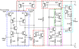
741 Circuit Identification
The 741 Circuit
The schematics of the 741 circuit is presented. It contains a reference current generator made with resistor R5, and transistors Ql1, Q12 and R5. Then R10 and transistors Q18 and Q19 make a voltage generator (2Vbe). The limiting of the output current is done by (R11, and transistors Q22 and Q24) and (R7 and transistors Q15 and Q21) Assume node Y (Q3 and Q4 transistor bases) is at V=constant and thus in alternating current is affectively at ground.
To do this the negative feedback loop is made with resistor R4 and transistors Q8. Q9, Q10.
1. Please find which 6 transistors work as emitter followers.
2. Please describe the functioning of the group (resistors R1-2-3 and transistors Q5-6-7).
3. What type of transistor amplifier is Q17?
4. What type of transistor amplifier is each of Q4 and Q3?

By Daniel Braun [GFDL, CC-BY-SA-3.0 or CC BY 2.5], via Wikimedia Commons
The emitter followers
They all have the load in the emitter and the collector connected directly to supply voltage. (Q1 and Q2 have their collector connected to the supply votlage through the current mirror Q8+Q9)
The current mirrors
2) The transitors Q5,6,7 and the resitors R1,2,3 form a so called modified Wilson Current Mirror. The transitors Q5 and Q6 (togheter with R1 and R2) make the active load of the input differential stage (Q1,2,3,4). The Wilson current mirror has one end closed (the end from the transitor Q5) by the transitor Q7. This is done to provide a single output (on the collector of Q6) of the entire load which is otherwise simetric.
3) Q17 has as load in the collector the internal resitance provided by the current mirror (Q12+Q13b). Having the load resistance in the ollector it is called a common emitter stage. Same, the 100 Kohm resitor in its emitter decreases gain but increases linearity.
4) Taken together Q3+Q4 are making a common base pair to eliminate the Miller Effect. Taken separately, because each Q3 and Q4 have the load in the collector (the stage decribed at point 2 above) they are connected in a common emitter configuration.

